In this article, the logic circuit, the truth table, and the working of half adder and full adder are explained.
Half Adder
The half adder is the logic circuit that adds the two bits and generates the sum bit (S) and carry bit (C) as an output. The truth table of the half adder is shown below.
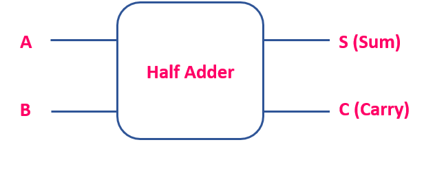

As per the truth table, the sum output is 1 for two input combinations. That means when A is 1 and B is 0 OR A is 0 and B is 1.
Algebraically, S = A’ B + A B’ = A ⊕ B
Likewise, the carry output is logic ‘1’ only for one input combination (when A = 1 and B = 1).
If we denote the carry output as C, then C = AB
Figure. 1 shows the Boolean expression and the logic circuit of the half adder.
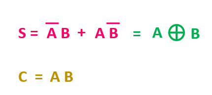

Fig. 1 The Boolean expressions and the logic circuit of the Half Adder
The half adder circuit is suitable for the addition of two bits at the LSB (Least Significant Bit) position. Because during the addition of two bits at the LSB position, there is no incoming carry. But whenever there is an incoming carry (Cin) along with the two bits, then a full adder circuit can be used.
Full Adder
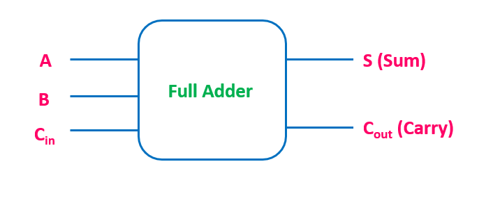
The full adder is the combinational circuit that adds the two bits along with the incoming carry (Cin) and generates the sum bit (S) and an outgoing carry bit (Cout) as an output. The truth table of the full adder is shown below.

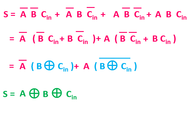
As per the truth table of the full-adder, the sum and carry outputs are logic ‘1’ for 4 different input combinations. So, let’s find the simplified algebraic expression of sum (S) and carry (Cout)
Similarly, using the K-map, it is possible to find the simplified boolean expression for the carry output. The K-map for the carry output of the full adder is shown below.

After the simplification, the carry output Cout = AB + B Cin + ACin
Moreover, the carry output can also be written as follows:
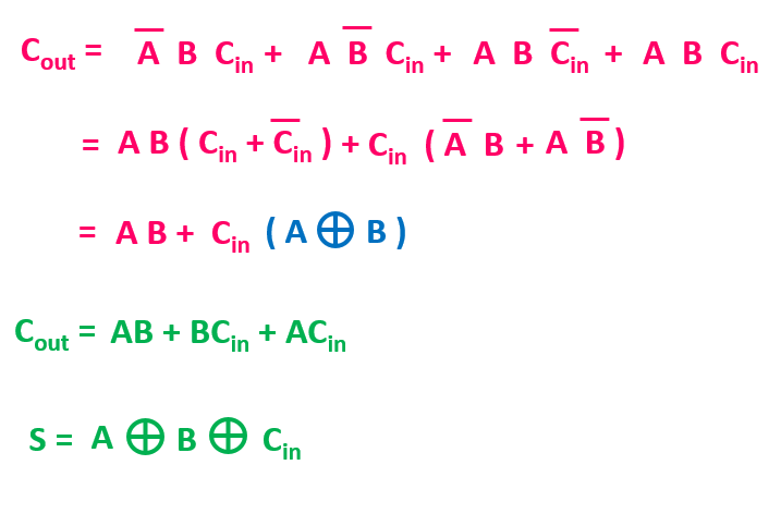
Based on these Boolean expressions, the logic circuit for the sum (S) and the carry (Cout) output is shown below.
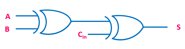
As it can be seen from the logic circuit, we require 5 two-input gates and 1 three-input gate to implement the full adder. So, in total, we require 6 logic gates. But using another expression of Cout (Cout = AB + Cin ( A ⊕ B) ), we can reduce the total number of gates.
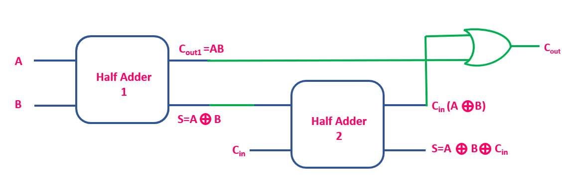
The same circuit is shown below. And if you closely observe then the circuit consist of two half-adders and one OR gate.

The same thing can also be shown in terms of the Half adder blocks.
For more information, do check this video on Half Adder and Full Adder.
very explanatory, thanks for your work!!