T Flip-Flop Symbol and Truth Table
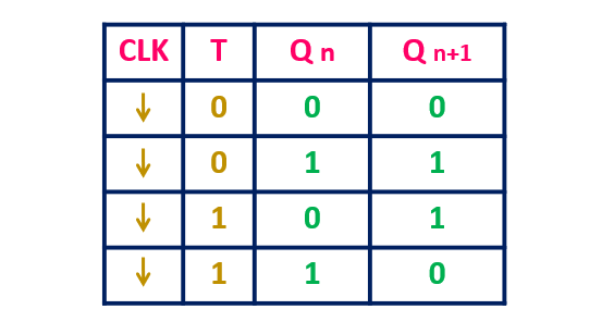
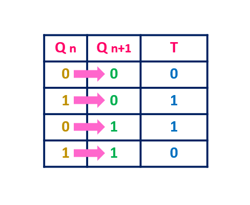
The T flip-Flop has one input. When the input is 1 then its output toggles. Let’s say the present state of the flip-flop is Qn. So, with T = 1, if Qn = 0 then in the next state, the output of the flip-flop Qn+1 will become 0. And similarly currently if Qn is 1 then in the next state, the output will become 0.
With T = 1 input, since the output of the flip-flop toggles at every clock pulse, so it is known as T flip-flop. When T = 0, then the flip-flop will remain in the same state. The symbol and the truth table of the T flip-flop is shown below.
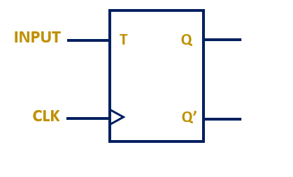

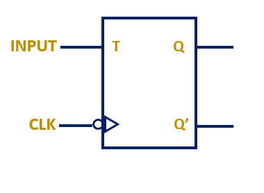
The symbol which is shown above is the symbol of the positive edge triggered flip-flop. The triangle in the symbol indicates that, the flip-flop responds to the input only at the rising edge of the clock. Similarly, the symbol of the negative edge triggered ?T flip-flop is shown below.
Characteristic Equation of T Flip-Flop
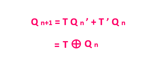
The characteristic equation of the flip-flop is the algebraic representation of the next state of the Flip-Flop (Qn+1) in terms of the present state (Qn) and the current input (T).
That means, here the input variables are Qn and T, while the output is Qn+1 .
From the truth table, as you can see, the output Q n+1 is 1 for two different input combination of Qn and T.

Let’s write down these two input combinations in the K-map, and let’s try to simplify the Boolean expression.
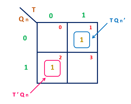
From the K-map, the two minterms are T Qn ‘ and T ‘ Qn . That means the characteristic equation of the T flip-flop is
Excitation Table of T Flip-Flop
The excitation table of the flip-flop shows the required excitation to the flip-flop, or the required input to the flip-flop, to go from the given state to the next particular state. For the T input, when T = 0 then the flip-flop remains in the same state and when T = 1 then the output of the flip-flop toggles at every clock pulse. The excitation table of the T flip-flop is shown below.
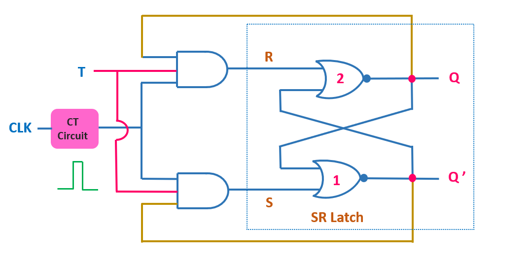
Circuit Diagram of T Flip-Flop
With the little modification, the JK flip-flop can be used as a T flip-flop. The truth table of the T flip-flop is shown below.
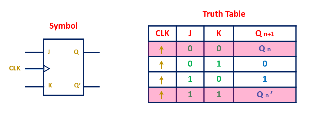
As you can see form the truth table, when both inputs of JK flip-flop are 0 then it hold the current state. And when its both inputs are 1, then the output of the flip-flop toggles. That means by connecting both inputs of the JK flip-flop together, it can be used as a T flip-flop.
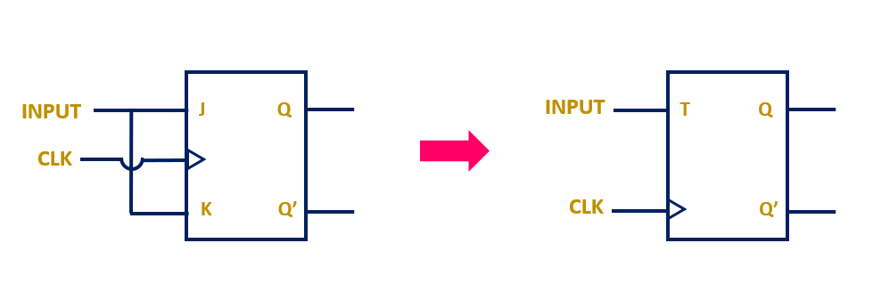
That means with the little modification in the circuit of the JK flip-flop, it can be used as a T flip-flop. The circuit of the T flip-flop is shown below.
For more information, check this video on T flip-Flop.