What is Logic Gate?
The logic gates are very basic building blocks of digital systems.
The logic gates are electronic circuits that consist of one or more inputs and one output. The relation between the input and output is based on certain logic. The logic gates have the ability to make certain logical decisions. And because of its ability to make these logical decisions, these gates are known as logic gates. By interconnecting or cascading the different logic gates, it is possible to implement various Boolean functions.
Types of Logic Gates
Here is the list of the different logic gates.
- AND
- OR
- NOT
- NAND
- NOR
- X-OR (Exclusive OR)
- X-NOR (Exclusive NOR)
The AND, OR, and NOT are three basic logic gates. Using these three gates, it is possible to design and logic circuits or it is possible to implement any Boolean function.
The NAND and NOR are Universal Logic Gates. Because using any of the two gates alone, it is possible to implement any Boolean function or logic circuit. Apart from that, the other two gates are X-OR and X-NOR gates.
AND Gate
The logic symbol and the Boolean expression of the AND gate are shown below.

The output of the AND gate is 1 when all the inputs are high or logic ‘1’. If any one of the inputs is low or logic ‘0’ then the output of the AND gate is low. The truth table of the AND gate is shown below.
Similar to the 2-input AND gate, more than 2 input AND gates are also available. The symbol of the 3-input AND gate and its Boolean expression is shown below.

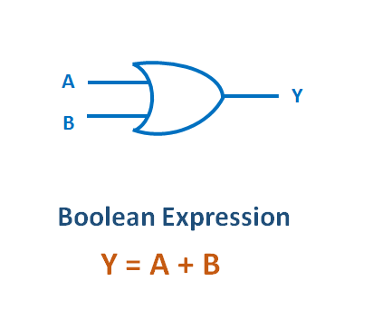
OR Gate
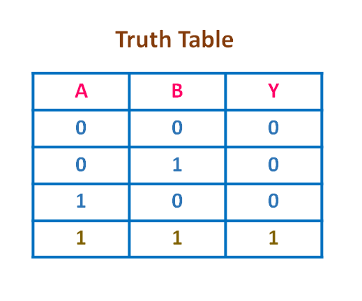
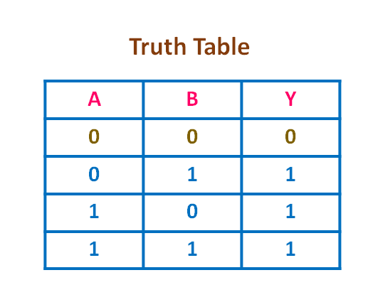
The logic Symbol and the Boolean expression of the OR gate are shown below.
The output of the OR gate is low or logic ‘0’ when all the inputs are low. If any one of the inputs is high then the output of the OR gate is high or logic ‘1’. The truth table of the 2-input OR gate is shown below.
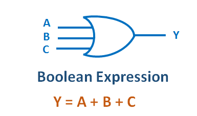
Similarly, we can also have an OR gate with more than 2 inputs. The logic symbol of the 3-input OR gate and the corresponding Boolean expression is shown below.
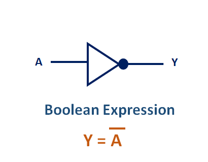
NOT Gate
The NOT gate is also known as the inverter gate. Because the output is the complement of the input signal. The logic symbol and the Boolean Expression of the NOT gate are shown below.
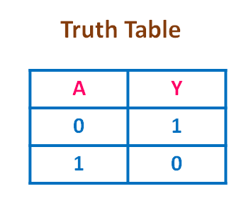
The NOT gate inverts the Logic ‘0’ to Logic ‘1’ and Logic ‘1’ to Logic ‘0’. The truth table of the NOT gate is shown below.
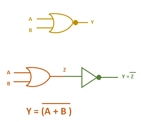
NAND Gate
The symbol of the 2-input NAND gate is shown below. It is similar to the AND gate, but there is a bubble on the output side. The NAND gate is the combination of the AND gate followed by the NOT gate. That means the output of the NAND gate is equivalent to the output of the AND gate followed by the NOT gate.
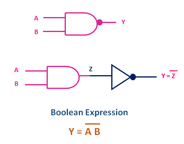
Logic Symbol and the equivalent logic circuit of the NAND gate
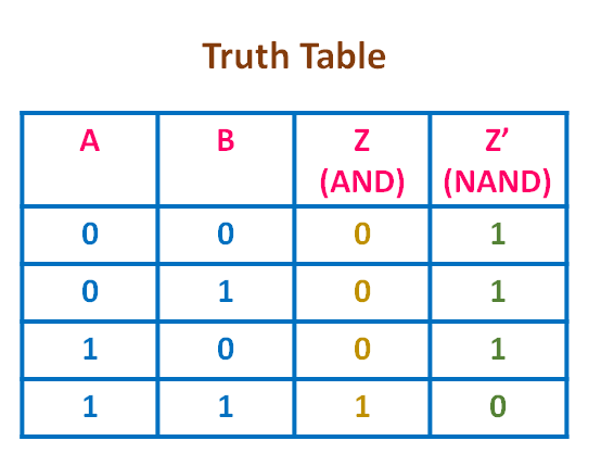
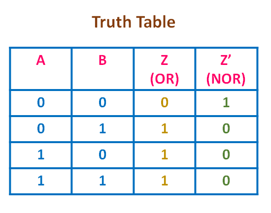
Here is the truth table of AND gate followed by NOT gate. The inputs are A and B. Z is the output of the AND gate, while Y is the output of the NOT gate. Z’ (Z- bar) is the same as the output of the 2-input NAND gate. The output of the NAND gate is logic ‘0’ when all the inputs are high. When any one of the inputs is logic ‘0’ or all the inputs are logic ‘0’ then output is logic ‘1’.
NOR Gate
The symbol of the 2-input NOR gate is shown below. It is similar to the OR gate, but there is a bubble on the output side. The NOR gate is the combination of the OR gate followed by the NOT gate. That means the output of the NOR gate is equivalent to the output of the OR gate followed by the NOT gate.
Here is the truth table of OR gate followed by NOT gate. A and B are the inputs. Z is the output of the OR gate. Y is the output of the NOT gate. Z’ (Z- bar) is the same as the output of the 2-input NOR gate. The output of the NOR gate is logic ‘1’ when all the inputs are low. When any one of the inputs is logic ‘1’ or all the inputs are logic ‘1’ then output is logic ‘0’.
For more information about the different logic gates, check this video.
XOR gate
The logical symbol and the truth table of the 2 input XOR gate are shown below.
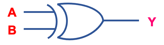
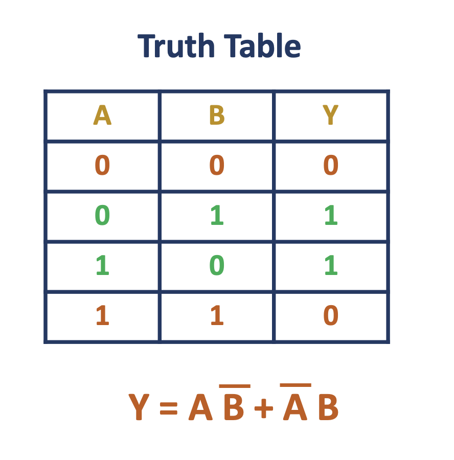
The Logic Symbol and Truth Table of 2 input XOR gate
As It can be seen from the truth table, the output of the 2-input XOR gate is logic ‘1’ when both inputs are different.
XNOR gate :
The Symbol of the 2-input XNOR gate is shown below. It is similar to the XOR gate, but there is a bubble at the output side. The XNOR gate is the combination of the XOR gate, followed by the NOT gate.

The logic Symbol and the Equivalent logic circuit of the XNOR gate
The truth table of the two-input XNOR gate is shown below. As you can see, the output of the two input XNOR gate is logic ‘1’ when both inputs are the same. when both inputs are different, the output is logic ‘0’.
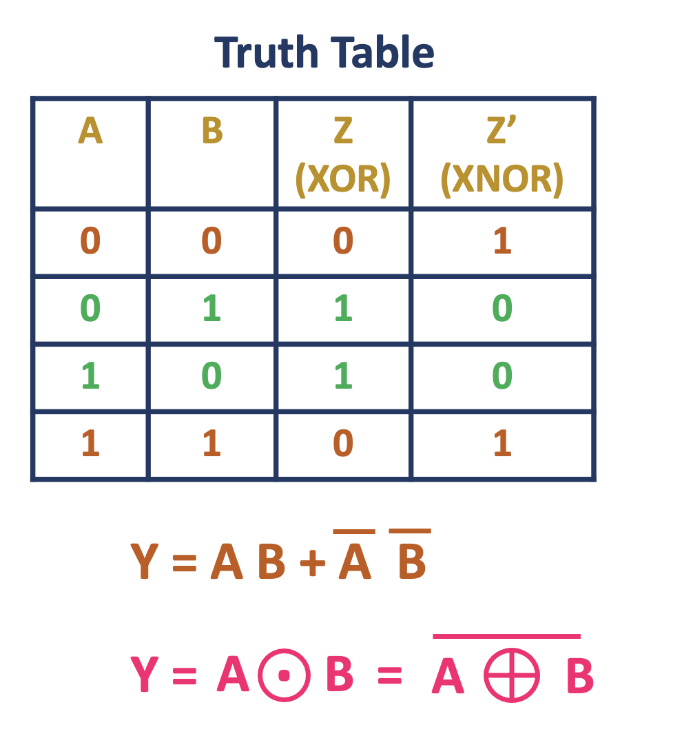
The Truth Table of the 2-input XNOR gate
These logic gates (XOR and XNOR) gates are very useful in designing the arithmetic and code converter circuits.
Typically, more than 2-input XOR and XNOR gates are not readily available and they are designed using the 2-input gates.
For more information about XOR and XNOR gate, check this video.
Awesome site for note taking stuffs. Request for more detailed notes on ipad platform of iit level notes.
GOOD