
The Master Slave Flip-Flop is the combination two gated latches, where the one latch act as a Master and the second one act as a slave. The salve latch follows the master output. Using the master slave configuration, the race around condition in the JK flip-flop can be avoided. So, let’s briefly see the race around condition in the JK flip-flop.
Race Around Condition in JK Flip-Flop
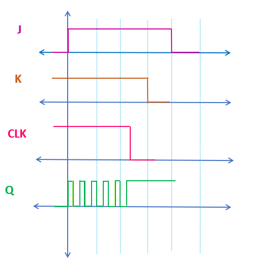
In the level triggered JK flip-flop when, when both J and K input are 1 and when the ON time of the clock is more than the propagation delay of the flip-flop then the output of the flip-flop will toggle continuously between ‘1’ and ‘0’. And because of that, it is difficult to predict the output of the flip-flop once the clock becomes low. The race around condition in undesirable condition in the flip-flop, and should be avoided to get the reliable flip-flop output.
Race Around Condition in JK Flip-Flop
Using the JK flip-flop in master slave configuration, this race around condition can be avoided.
Circuit Diagram of Master Slave JK Flip-Flop
Circuit Diagram of Master Slave JK Flip-Flop
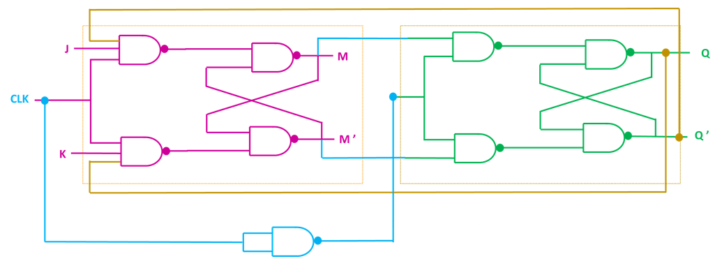
As shown in the above figure, it consist of two gated SR latches. The first latch act as a master latch and the second latch act as a slave latch. The output of the master latch is connected to the slave latch. The Q’ output of the slave latch is connected back to the master latch where J input is applied and similarly, Q output is connected back where the K input is applied. The clock signal to the slave latch is applied through an inverter. That means when clock signal is high then master is enabled and slave is disabled. And similarly, when clock is low then slave is active and master is disabled.
Working of Master Slave JK Flip-Flop
Let’s understand the working of Master Slave JK flip-flop using timing diagram.
Timing Diagram of Master Slave JK Flip-Flop
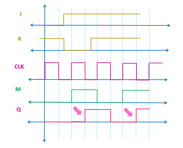
Here, initially it has been assumed that the outputs of both master and slave are 0. (Both M and Q are 0). When the clock signal is high then master latch will get enabled and will respond to the input signals. In this case, initially during the first clock, J = 0 and K = 1. So, output of the master latch will be 0. During ON time of the clock, the slave latch will remain disabled and it will hold its current state. Similarly, during the OFF time of the clock, the master will get disabled and it will hold its current state. And at the same time, the slave latch will become active and will follow the master output. That means, the slave latch is following the master output during the off time of the clock. Or in other words, the slave latch follows the master output after the delay of TON . Where TON is the ON time of the clock signal. This cycle repeats at every clock cycle.
During the ON time of the second clock, since J = 1 and K = 0, so master output M = 1. And the slave output Q will remain 0. (Since it is disabled) The slave latch will follow the master output during the OFF time of the clock. From the timing diagram, you can see that, the slave is following the master output after the delay of TON.
For more information, please go through this video on the master slave flip-flop.
Master Slave SR Flip-Flop and D Flip-Flop
Similar to the master slave JK flip-flop, the master slave D flip-flop and SR flip-flop can be designed.
The circuit diagram of the master slave SR flip-flop is shown below.

Master Slave SR Flip-Flop
In a simplified manner, this is how it can be represented.

Similarly, using two gated D latches, the master slave D flip-flop can be designed.
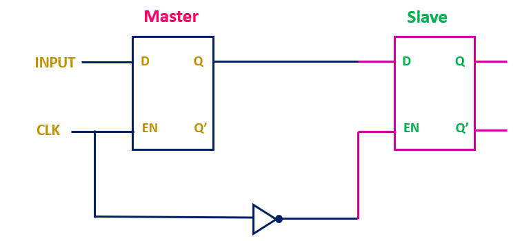
Master Slave D Flip-Flop
The master slave flip-flop circuit works correctly when the input is constant during the ON time of the clock. If the input signal changes during the ON time of the clock, then slave will not be able to follow the master output. The same is shown in the below timing diagram.
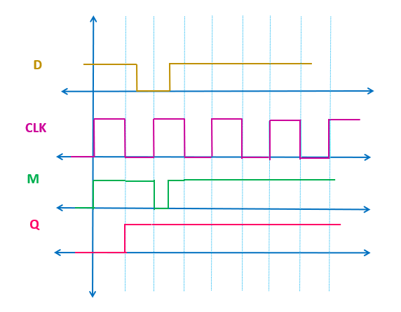
As you can see in the timing diagram, during the second clock cycle, the D input is changing during the ON time of the clock. Since the master is ON at that time, so master will follow the change in the input signal. But the slave will not be follow that input change. Because the slave is following the master output during the OFF time of the clock. Just at the end of the ON period of the second clock, the master output M is 1, so slave will follow the same output. That means, the slave is not able to follow the master output completely when the input is changing during the ON time of the clock.
That means, to use the master slave flip-flop in a correct manner, we need to ensure that the input is not changing during the ON time of the clock.
VERY NICE EXPLANATION ABOUT MASTER SLAVE FLIP FLOPS.
THANKS A LOT
kindly plz. provide such a nice notes on shift register and counters also.