What is optocoupler?
The optocoupler is a circuit/circuit component that optically couples the signal from one circuit to the other circuit and provides electrical isolation (Galvanic isolation) between the two circuits.
Since it provides the electrical isolation between the two circuits, it can be used for protecting very important low voltage circuit block from other circuits which is prone to the high voltage spike, noise or ground loops.

Applications of Optocoupler
- To provide electrical isolation between two electrical circuits
- Prevent very important low voltage circuit from noise, ground loops, and high voltage spikes
- To control the high voltage circuit using a logic circuit or micro-controller (keeping electrical isolation between them)
- Communication Systems
- Solid State Relays
- Power Supplies
What’s Inside Optocoupler?
A typical optocoupler consists of two elements. The Infrared LED and Photosensitive device. The photosensitive device can be a photo-transistor, photo Darlington pair, photo-SCR, or photo Triac. The LED and photosensitive devices are integrated into a single package and for optimal coupling, their spectral response or wavelengths are tightly matched.

How Optocoupler Works?
On one side of the optocoupler, when an electrical signal is applied to the LED, the LED converts the electrical signal into an optical signal. The LED light falls on the photosensitive device and it converts the optical light into the electrical signal. (It generates the photocurrent). When light falls on the photo-sensitive device, it conducts and allows the flow of current. And the same current also flows through the external circuit which is connected with the photodetector. In this way, the optocoupler optically couples the signal of one circuit to the other circuit.
The electrical signal could be an analog signal or a digital signal. For analog signals, to achieve good linearity between the input and output, linear optocouplers are used.
Optocoupler Specifications
While selecting the optocoupler for a specific application, one should also check the specifications of the optocoupler. Here is the list of some of the important specifications of optocoupler.
1. Forward Current and the Forward Voltage
In the datasheet, the absolute maximum rating for various parameters is specified. One such parameter is the forward current of the LED. The current through the LED should be less than the maximum specified limit.
In the datasheet, the typical value of the forward voltage drop across the LED is also mentioned.
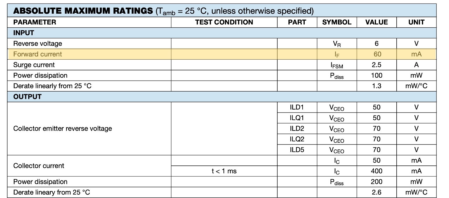
Based on the input voltage and the typical forward voltage drop across the LED, one can decide the series resistor for the LED for the specific current. But the current should not exceed the maximum specified value of the current in the daatsheet.
2. Current Transfer Ratio (CTR)
The current transfer ratio is the ratio of the output collector current (In case of the photo-transistor) to the input forward current of the LED in the optocoupler.
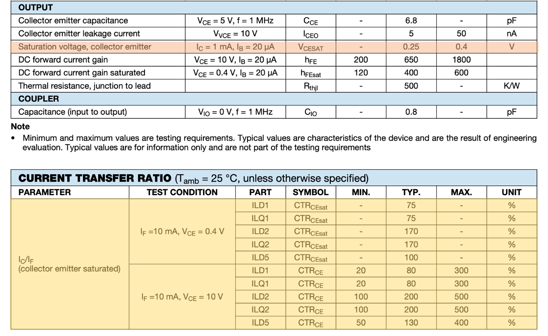
The CTR changes with photo-sensitive devices. The different photo-sensitive devices (like photo-transistor, photo SCR, photo Darlington pair) have different output currents and hence different current transfer ratios. But for the given, photo-sensitive device, it is the function of temperature, the forward current of the LED, and the output biasing voltage.
3. Switching Characteristics
When optocoupler is used for the switching application then this characteristic is very important. Under this characteristic, the typical rise-time and fall-time for the optocoupler is specified in the datasheet. The rise-time and the fall-time decide the maximum switching frequency of the optocoupler.
4. Maximum Isolation Voltage
It is the maximum RMS voltage up to which it provides the isolation between the two sides of the optocoupler. Typically, this isolation voltage is specified in kV. The datasheet also mentions the peak transient voltage. It is the peak transient voltage up to which it provides the electrical isolation between the two sides of the optocoupler.

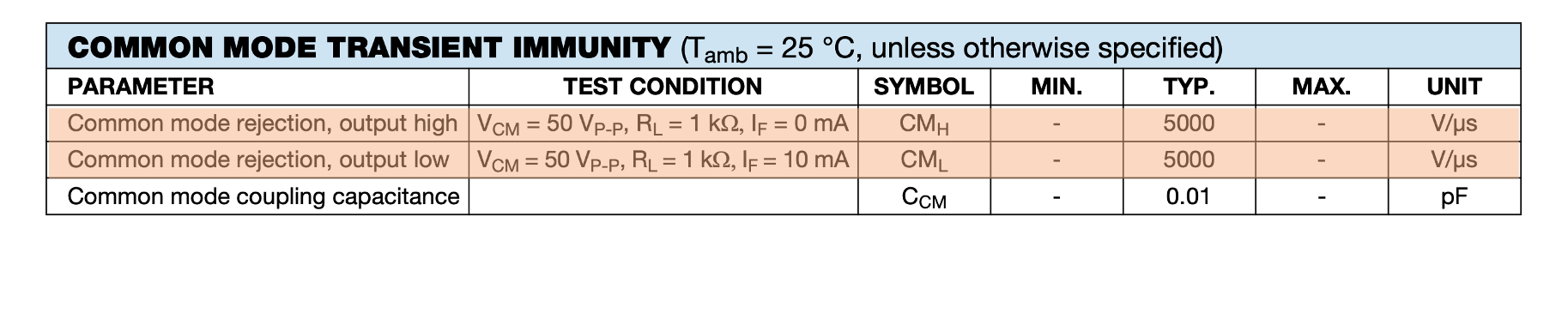
5. Common mode Transient Immunity
The optocoupler should be able to reject the common mode noise and common mode transient noise. The common-mode noise is noise which presents on the both input and output side of the optocoupler. The optocoupler datasheet mentions the common-mode transients (V /µs) up to which it provides immunity.
Difference between Relay and Optocoupler
Functionality wise the relays are very similar to the optocoupler as they provides the electrical isolation between the two circuits. And using relay, it is possible to control the high voltage circuit using low voltages. But there are some differences between relay and optocoupler.
- Optocouplers are typically faster than Relay (Relays are used for slow switching applications)
- Optocouplers work with both analog and digital signals. The optocouplers can be used in switching applications as well as to transfer the analog signal from one circuit to the other circuit. While relays are typically used for switching applications.
- The relays can work with high current and high power loads. The optocouplers are typically used for low power applications.
- Since optocoupler does not contain any mechanical part like relay, the life span of optocoupler is longer than relay.