What is Cascode Amplifier?
The Cascode Amplifier is the combination of the common source (Common Emitter for BJT) and the Common Gate Stage (Common Base for BJT). As shown in Fig. 1, the input is applied to the common source amplifier.
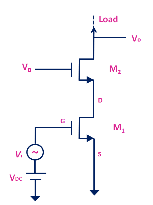
Fig.1 Cascode Amplifier
The transistor M1 is also known as amplifying transistor. And the output of this transistor is fed to the common gate stage (M2). The output of the cascode amplifier is measured at the drain terminal of the common gate stage (M2). For a time being here, the load is not shown. But the load could be a passive resistive load or it could be an active load like a resistor.
The Cascode amplifier provides high intrinsic gain, high output impedance and large bandwidth.
Output Resistance of Cascode Amplifier:
The common gate stage multiplies the output resistance of the common source stage. If ro1 is the output resistance of the transistor M1, then the output resistance seen from the drain terminal of the M2 is approximately gm2ro2ro1.
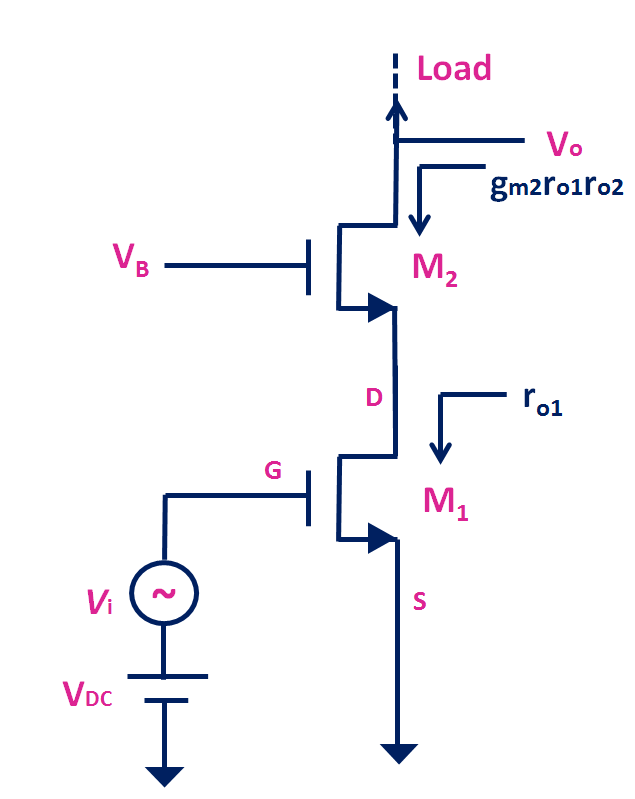
Fig. 2 The output resistance of the Cascode Amplifier
Because of its higher output impedance, the intrinsic gain of the cascode amplifier is also very high.
Intrinsic Gain of Cascode Amplifier:
The intrinsic gain of the cascode amplifier can be found by finding the overall transconductance of the cascode stage. If Gm is the transconductance of the cascode stage and Ro is the output resistance of the cascode amplifier then intrinsic gain Ao = – Gm Ro
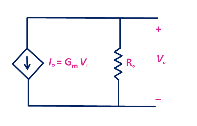
Fig.3 The output equivalent circuit of the Cascode Amplifier without load
For the cascode stage, the transconductance Gm ≈ gm1 and Ro ≈ gm2 ro2 ro1. Therefore, the intrinsic gain |Ao| = gm1gm2ro1ro2. The intrinsic gain of the Cascode amplifier is significantly higher than the common source amplifier. The overall voltage gain of the cascode configuration depends on the load.
Cascode Amplifier with Resistive Load
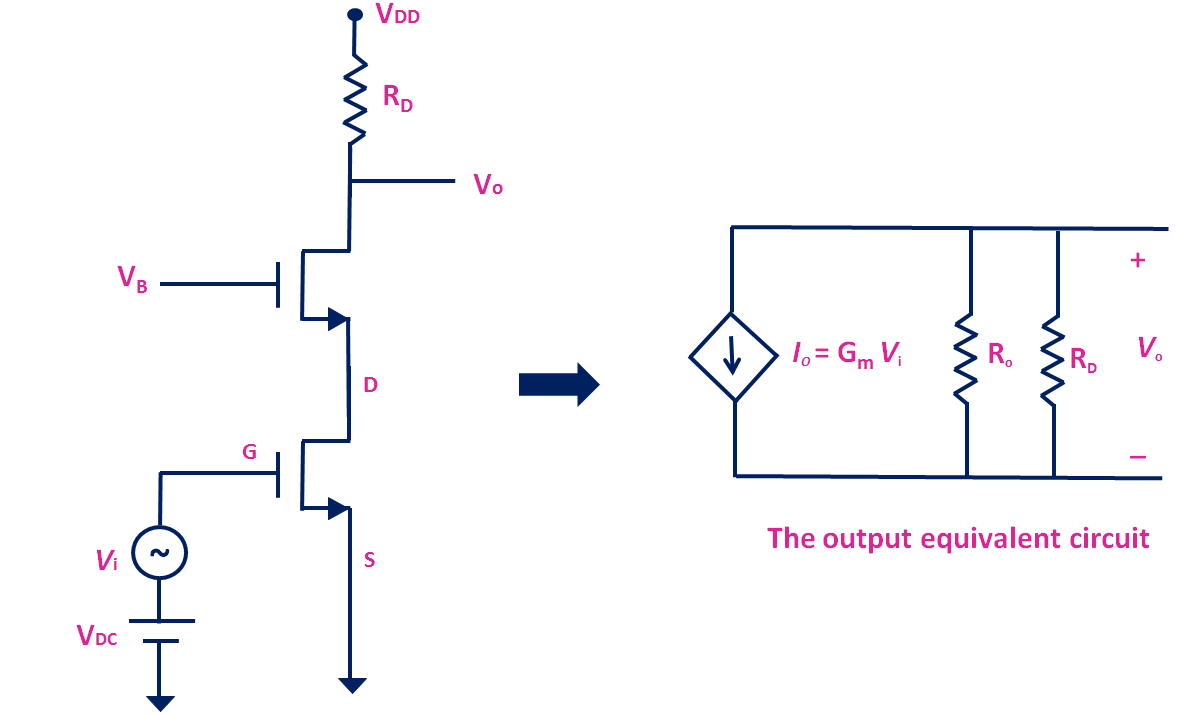
Fig. 4 Cascode Amplifier with resistive load
Fig.4 shows the cascode amplifier with the resistive load and the output equivalent circuit. In this case, the voltage gain |Av| ≈ gm1 ( Ro|| RD). Where Ro is the output resistance of the cascode stage. Typically Ro >> RD. Usually, RD is in kΩ, while Ro is in MΩ. Therefore, |Av| ≈ gm1 RD. It is typically the same as the common source amplifier with resistive load.
Cascode Amplifier with current source as a load
The higher gain can be achieved using the active load. As shown in Fig.5, if the active load is the ideal current source then, the voltage gain |Av| = gm1 Ro.
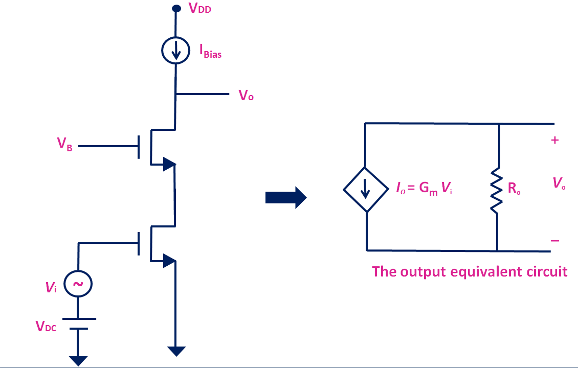
Fig.5 The cascode amplifier with ideal current source as a load.
But the actual current source has finite output resistance. And due to the finite output resistance, the overall voltage gain reduces. Fig.6 shows the cascode amplifier with PMOS as a current source. Where Ro1 is the output resistance of the cascode stage and ro2 is the output resistance of the PMOS.
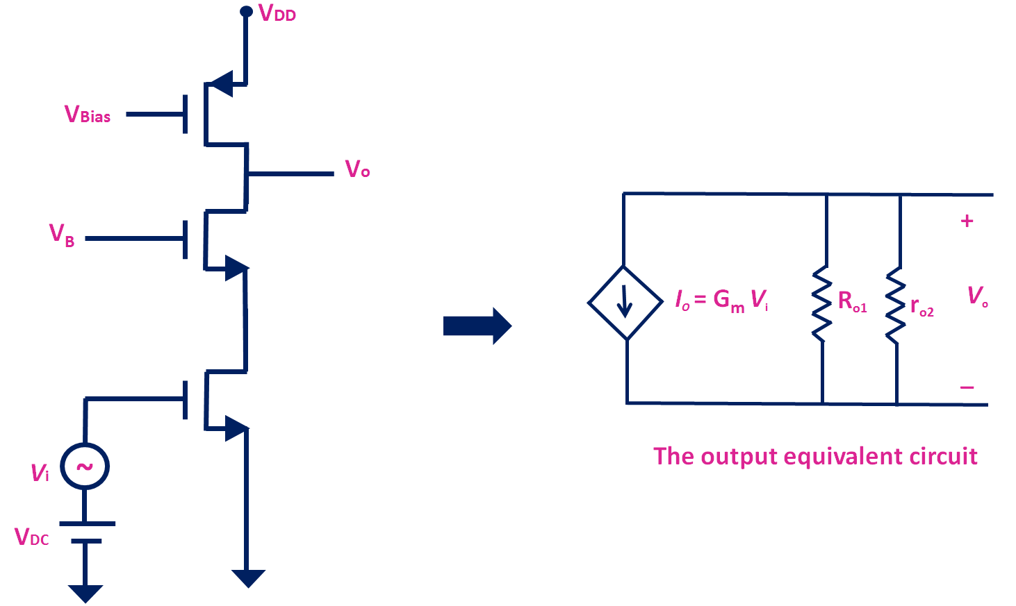
Fig. 6 The Cascode Amplifier with PMOS as a current source
With PMOS current source as a load, the voltage gain |Av| ≈ gm1 ro2. Because the output resistance Ro1 of the cascode stage is much greater than the output resistance of the PMOS. Typically, with this arrangement, the achieved voltage gain is similar to the intrinsic gain of a common source amplifier. To further improve the gain, the cascode current source can be used as a load with cascode amplifier.
Cascode Amplifier with Cascode current source
Fig. 7 shows the typical Cascode current source using PMOS transistors.
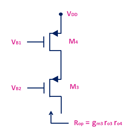
Fig. 7 Cascode current source using PMOS transistor
The output resistance seen from the drain of M3 transistor is approximately equal to gm3 ro3 ro4. Which is typically much higher than the output resistance of the single PMOS transistor.
Fig. 8 shows the cascode amplifier with the cascode current source as a load.
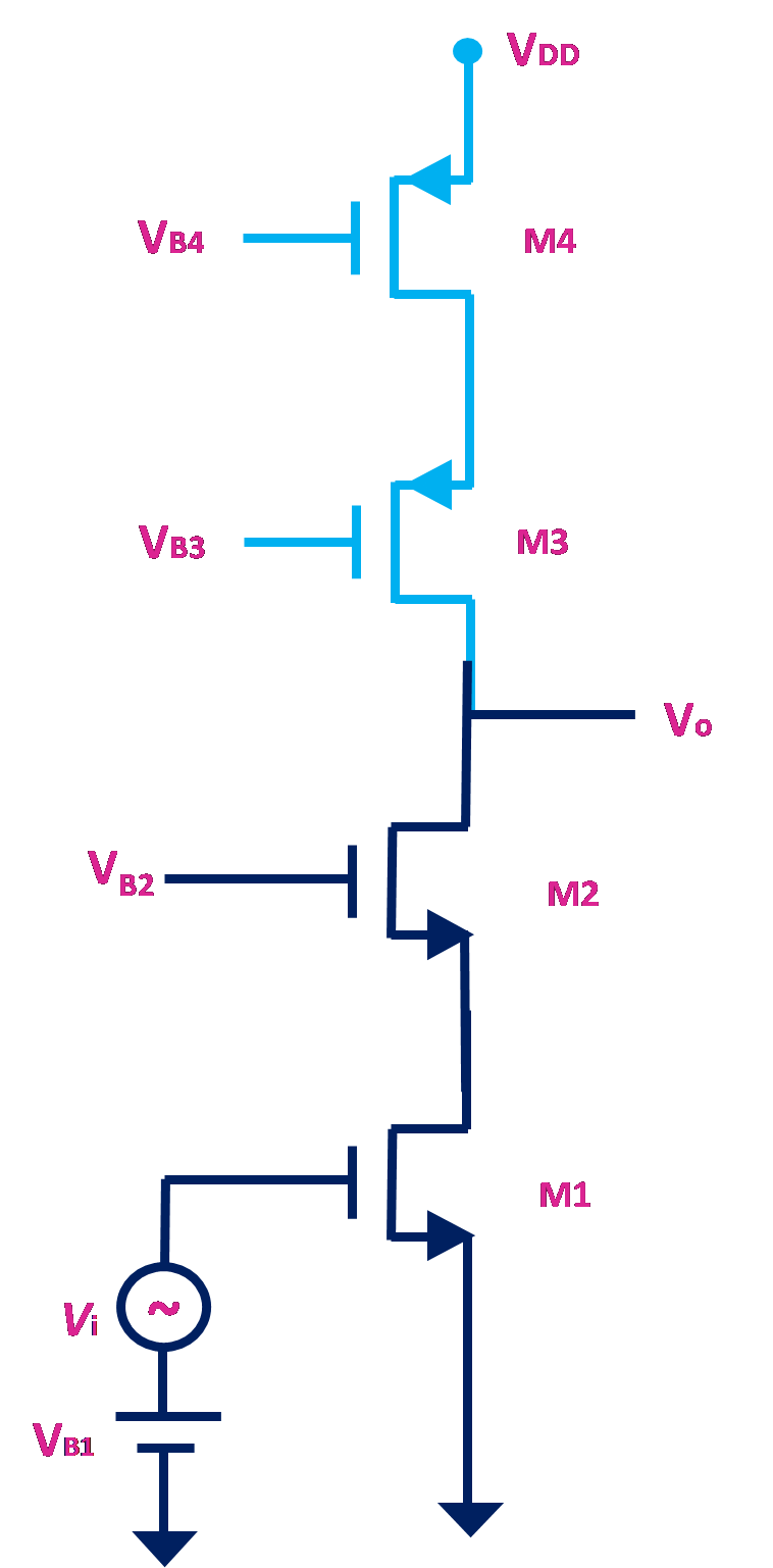
Fig. 8 Cascode Amplifier with Cascode Current Source
With Cascode current source as a load, the voltage gain of the cascode amplifier |Av| ≈ gm1 ( Ron || Rop)
Where, Ron = gm2 ro2 ro1 is the output impedance of the cascode amplifier stage, and Rop = gm3 ro3 ro4 is the output resistance of the cascode current source. Using the cascode amplifier along with the cascode current source, the gain of the amplifier can be improved significantly. And typically, this configuration is used in the integrated circuits to achieve a large gain.
For more information, and for small-signal analysis, check this video: