What is Current Mirror?
The current mirror is an analog circuit that senses the reference current and generates the copy or number of copies of the reference current, with the same characteristics. The replicated current is as stable as the reference current source. The replicated current could be the same as the reference current (Icopy = IREF), or it could be either multiple or fraction of the reference current. (Icopy = N*Iref or Icopy = (1/N)*IREF).

Fig.1 Basic function of Current Mirror Circuit
Why Current Mirrors are used?
Current Mirrors are particularly useful in the integrated circuits, for biasing the amplifiers. The advantage of biasing the amplifiers with the current source is that it provides a high voltage gain and good biasing stability. This current source can be generated using a simple PMOS transistor or using a MOS transistor in cascode configuration (to achieve higher gain) as shown in Fig.2.
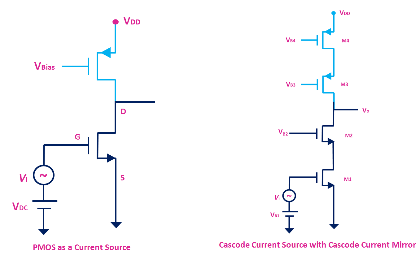
But this type of MOS current source (shown in Fig.2) is susceptible to the change in the biasing voltage and the change in temperature. Moreover, the integrated circuit may contain hundred or thousand of such amplifiers. To bias all the amplifiers with precise biasing voltage is another challenge. So, to overcome all these problems, in integrated circuits, one stable current source is fabricated within IC, and using the current mirror the multiple copies of the stable current source is generated (which can be used to bias the amplifiers)
MOSFET- Current Mirror
Fig.3 shows a current mirror circuit using the NMOS transistor. The reference current is converted to the voltage using diode connected transistor and the same is applied between the gate and the source of the another MOSFET.
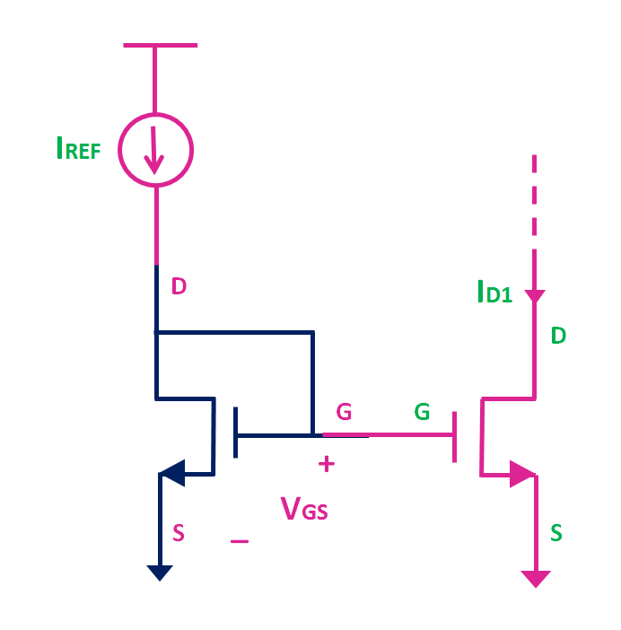
Fig.3 Current Mirror Circuit using NMOS transistors
The relation between the ID1 and IREF can be given by the following expression.

By changing the W/L ratio of the two transistors, the current which is fraction or multiple of the reference current can be generated. The only thing which needs to be ensured is that, the MOSFET should operate in the saturation region.
Effect of Channel Length Modulation on Current Mirror
So far during the discussion, the effect of channel length modulation was neglected. If the channel length modulation effect is also considered, then as shown in Fig. 4, as the drain to source voltage (VDS) of the MOSFET increases, the drain current also slightly increases.
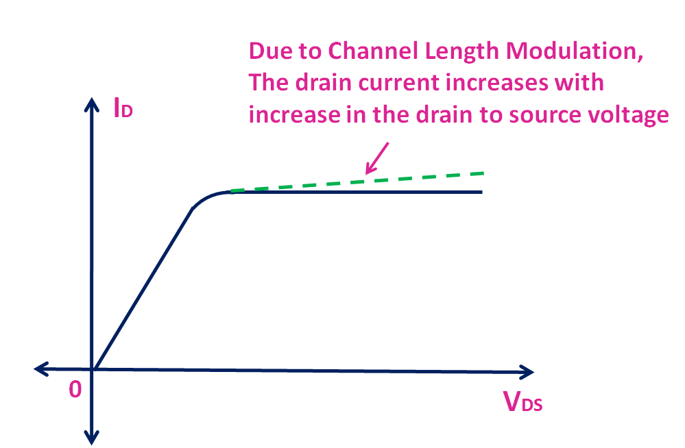
Fig.4 The effect of channel length modulation on drain current of the MOSFET
Considering the channel length modulation effect, if VDS of MOSFET M1 changes by ΔVDS then the drain current ID1 also changes to ID1 + ΔID1. The same is shown in Fig. 5.
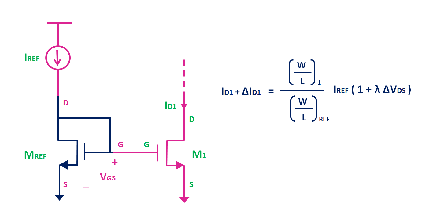
Fig. 5 Effect of Channel Length Modulation on Current Mirror
The effect of channel length modulation can be reduced by increasing the length of the channel for the given W/L ratio.
PMOS Current Mirror
Fig. 6 shows the implementation of current mirror using the PMOS transistors. In PMOS current mirror, the source terminals for both transistors are connected to Supply voltage Vdd.

Fig. 6 Current Mirror using PMOS transistors
The relation between the ID1 and IREF can be given by the same expression.
The only thing which needs to be ensured is that M1 should operate in the saturation region. Or in other words, VSD1 ≥ VSG – |VTP |, Where VTP is the threshold voltage of the PMOS transistor.
Current Steering Circuit
Fig. 7 shows the current steering circuit, which can be used to drive different amplifiers. And using this circuit is possible to generate a bias current which is multiple or the fraction of the reference current source.
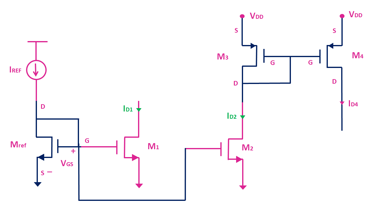
Fig. 7 Current Steering Circuit Example
For example, let’s say (W/L)1 = 2 x (W/L)REF , (W/L)2 = (W/L)3 = 3 x (W/L)REF and (W/L)4 = 6 x (W/L)REF.
Therefore, ID1 = 2 x IREF and ID2 = 3 x IREF. The same current ID2 will also flow through the transistor M3. Therefore, ID3 = ID2. And since (W/L)3 = 3 x (W/L)REF and (W/L)4 = 6 x (W/L)REF, ID4 = 2 x ID3 or ID4 = 6 x IREF. (assuming μn Cox = μp Cox, and overdrive voltage for M2 and M3 are equal)
So, in this way, by changing the W/L ratios, it is possible to generate a multiple or fraction of the reference current. And the same can be used to drive different circuits. For example, current ID1 can be used to drive a source follower circuit and current ID4 can be used to drive a common source amplifier. The same is shown in Fig. 8.
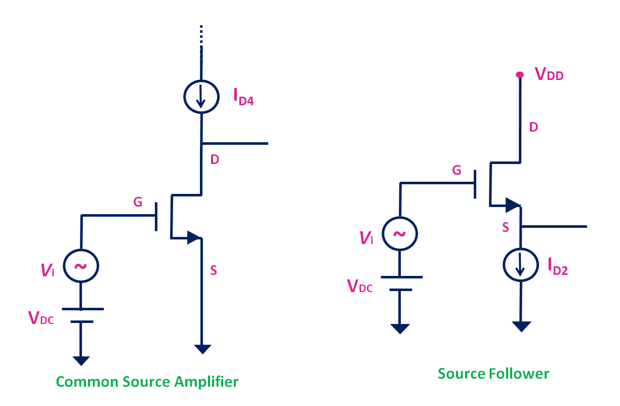
Fig. 8 Curent Mirror as an active load for the amplifiers
Typically in the integrated circuits, the amplifiers are biased as shown in Fig. 8. Where current ID4 and ID3 are derived using the current mirror circuits. This type of arrangement provides good biasing stability. But to further improve the gain of the amplifier, the cascode current mirror circuits are used and the same is used as an active load with the MOS amplifiers.
For more information, please check this video on Current Mirror:
yes we want more knowledge regarding the current mirror please make a video in the video you said that you provide some examples with numerical please make a video on it
Nice explanation, thanks!